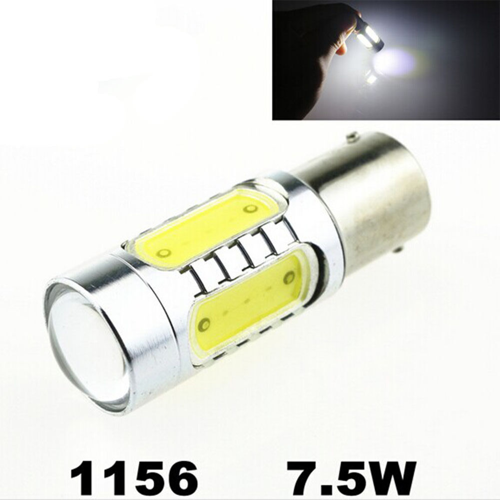
Fixing your flasher relay after installing LED indicator lamps on your Toyota Hiace (1996)Ok, so I have installed a total of four 7.5W amber LED indicator bulbs at the back and on the front bumper, and plan to install some more LEDs at the front for the short T10 repeaters below the running/turning lights.
I had to de-rust and liberally grease the front bumper bulb sockets - worth checking yours.
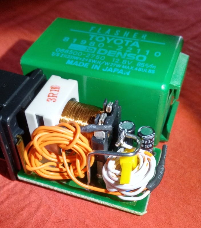
LEDs (4x21W -> 4x7.5W) somewhat lowers the current drawn, so the Nippon Denso Toyota flasher relay (81980-22110) then thinks there is a blown bulb and goes into 'hyper flashing'. Which is much too fast for the MOT (I suspect), and a bit irritating. You can add resistors, but frankly that's an awful idea on many levels, so lets just fix the problem at source.
Getting it outThe flasher relay is just under the meter dial in the dash. To unclip it from the metalwork, push the bit near the front of the car (with the connector on it) down, which will release the tab at the back - nearest you, so you can jiggle it up and free. Then you need to unplug it - which in this case, is just a firm disconnection - no tabs are used.
Much research was carried out on the internet and due to the total lack of any specs about the chip used, (a Nippon Denso SE051) the other idea, of making the sensor resistance bigger was used.
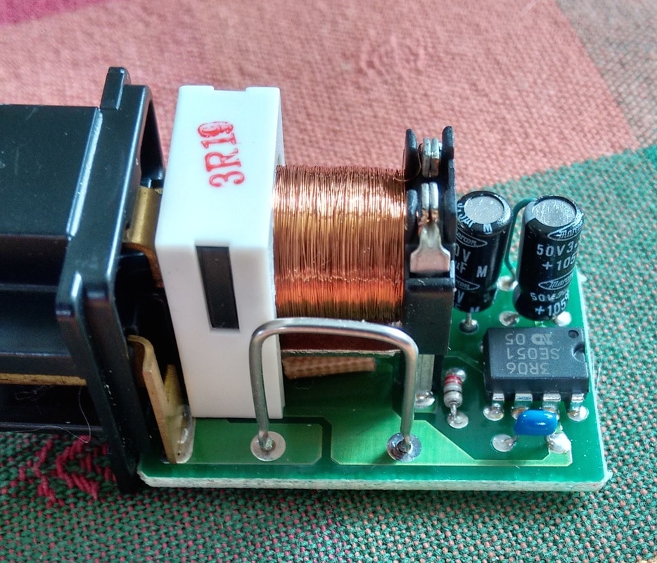
When you slip the green cover off you'll see a metal loop. This isn't made of copper so it has a certain resistance, but my meter couldn't detect any - so it was less than 0.01ohm. However, this is the current sensing resistor.
SurgeryUnsolder one end of the loop and bend the other end carefully to it will still fit in the case, but so you have space for more wire. More wire == more resistance, fooling the current sensor to detect more current.
Obtain some CAT5 cable - mine had 0.5mm (22awg) solid copper - so make sure yours is the same. Cut off 1.1m of it, and wind half into a coil on a pen, then change direction and wind the 2nd half on the same pen but the opposite way. This creates a 1.1m length of inductance free resistance.
Trim both ends to 4mm bare copper (nick with a knife and pull with your nail), and solder one end to the free end of the old metal loop, and the other end to where the loop used to go. You now have a 1.1m length of 0.5mm copper in series with the old resistance, to allow for the lower current. Neatly tuck it up and pop the assembly back in the green case.
Note - mine looks messier as I tried various combinations to arrive at the perfect mix:
For neatness I'd suggest opening out the other side of the loop when you do it.
UsageThis has been tested in my Hiace with hazards and with a single side - with headlamps on - the worst (lowest voltage) case - and found to work perfectly, so I'd expect it to work fine for you too.
NotesIf you run smaller LEDs than 7.5W you may need thinner or longer wire, or wire made of nickel etc - i.e. wire of more resistance. However I can testify the 7.5W LEDs are magnificent, you _need_ these bulbs.
They took ages to arrive, but were worth it.
http://www.ebay.co.uk/itm/111759953323
I've found LEDs mounted on billet aluminium very bright and these are no exception.
Also note that other sites suggest just grinding that loop a bit thinner, that will also work. You just need to lower the conductance (raise the resistance) of that loop.